Components / Inductors

Inductors: Inductance, Current and Saturation

Read inductance, DC resistance, saturation current and thermal current limits.

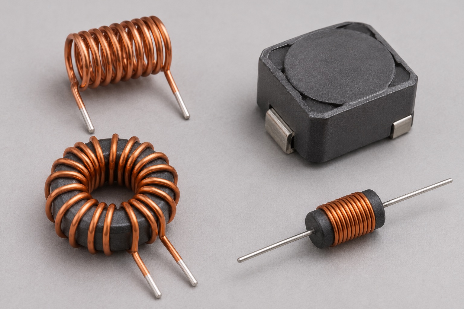
Illustrated inductor forms: open copper air-core coil, shielded surface-mount power inductor, ferrite toroid and axial leaded choke
Appearance illustration of 4 common physical forms. Generated for teaching, not a photograph of the models below; size and markings are not exact. See the in-site model notes for verified details.

Recognise and choose

What forms will you encounter?

01Bare copper coil, upper left

Air-core coil

How to recognise it
Visible turns of wire without a magnetic core.
Use it when
Radio-frequency matching and tuned circuits when high Q and no core saturation are valuable.
Check before choosing
Inductance at test frequency, Q, self-resonant frequency and mechanical spacing.

Model notes on this siteCoilcraft 1515SQ series →

02Dark block, upper right

Shielded SMD power inductor

How to recognise it
Compact square or rectangular moulded body, sometimes with a value mark.
Use it when
Switching regulator energy storage when board area and stray magnetic field matter.
Check before choosing
Inductance, DCR, peak saturation current and RMS thermal current under stated conditions.

Model notes on this siteCoilcraft XAL4020-102 →

03Copper-wound ring, lower left

Toroidal wound inductor

How to recognise it
Wire wrapped around a doughnut-shaped magnetic core.
Use it when
Power filters or chokes where the closed core path helps contain magnetic flux.
Check before choosing
Core material, inductance versus bias, saturation, winding temperature and insulation.

Model notes on this siteCoilcraft SPT series →

04Small striped cylinder, lower right

Axial leaded choke

How to recognise it
Resistor-like cylinder with a lead at each end; colour bands do not make it a resistor.
Use it when
Through-hole low-current filtering where axial mounting is convenient.
Check before choosing
Inductance, rated current, DCR and self-resonant frequency.

Model notes on this siteCoilcraft PCH-45 series →

At a glance

An inductor stores energy in a magnetic field and opposes a sudden change in current. Power inductors need both peak-current and heating checks.

This guide explains a component family. Check the exact part number and manufacturer datasheet before building.

Key specifications

Inductance
Nominal L, measured at specified test conditions
Saturation current (Isat)
Current at a stated loss of inductance
RMS current (Irms)
Current producing a stated temperature rise
DC resistance (DCR)
Winding resistance that contributes to copper loss

Circuit Lab

Put this component into a circuit

What changes as a coil approaches its current limit?

Change
Inductance, DCR, applied voltage and current limit
Observe
Current slope, stored energy and copper loss

Explore the linked experiments using their stated model assumptions. Device-specific limits still come from the linked datasheets.

How it works

For an ideal inductor, v = L × di/dt and stored energy is ½ × L × I². In a switching converter, current rises and falls each cycle; the magnetic core and winding must tolerate both the peak and the RMS current.

Types and construction

Ferrite-core power inductors provide high inductance in a compact size, while air-core parts avoid core saturation but may be larger. Shielded constructions can reduce stray magnetic field. RF inductors also require attention to self-resonant frequency and Q.

Worked example

With an ideal 100 µH inductor and 1 V across it, current changes at 10,000 A/s, or 10 mA per microsecond. This slope assumes L stays constant; near core saturation the slope rises as effective inductance falls.

Reading a datasheet

Compare inductance at the specified frequency and bias, the exact Isat definition, Irms temperature-rise condition, DCR, operating temperature and self-resonant frequency. Isat and Irms are different limits and neither replaces the other.

Common mistakes

  • Choosing by nominal inductance and ignoring peak current.
  • Comparing Isat numbers without checking each maker’s permitted inductance drop.
  • Using only average current to predict winding temperature.

Explore further

Source and review

Reviewed 18 November 2026 against Coilcraft, Selecting the Best Inductor for Your DC-DC Converter. Examples are simplified educational models; ratings and pinouts depend on the exact device.