
01 / CALCULATOR
LED Resistor Calculator
Choose a standard current-limiting resistor and check its actual current and power.
From your first resistor to your next idea
Your electronics workbench for calculating values, getting to know components, and exploring how circuits work. Start with a question. Build your understanding.
Start with a value
Choose a standard current-limiting resistor and check its actual current and power.
Solve voltage, current, resistance, and power from any two independent values.
Compare unloaded and loaded output voltage, current, and resistor power.
Follow a task
Estimate a resistor, then understand how resistance and LED forward voltage affect current.
Calculate an LED resistor →Calculate a divider, connect a load, and compare the output.
Run the experiment →Read ratings and markings before you build a simple low voltage circuit.
Explore components →Circuit Lab · free wiring + 8 guided experiments
Change Vin, R1, R2, or RL in a fixed topology DC model. The measurements come from the same divider equations as the calculator.
Open loaded divider →Same source. Different load. A different result.
Build and explore
Free wiring
Draw your circuit, run it, inspect voltage and current, and save or export your work.
Guided experiment
Change the series resistor and LED forward drop to compare current, power, and an illustrative LED glow.
Guided experiment
Move through time as a capacitor charges or discharges. Compare capacitor voltage, resistor voltage, and current.
Understand the parts
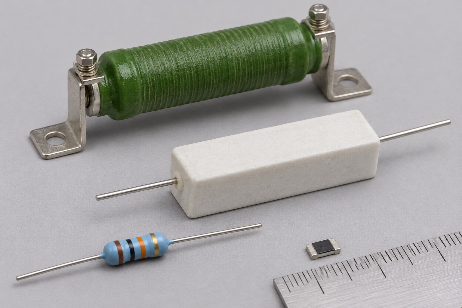
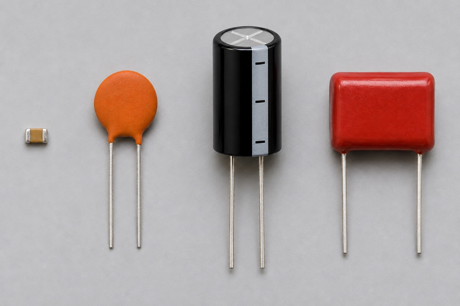
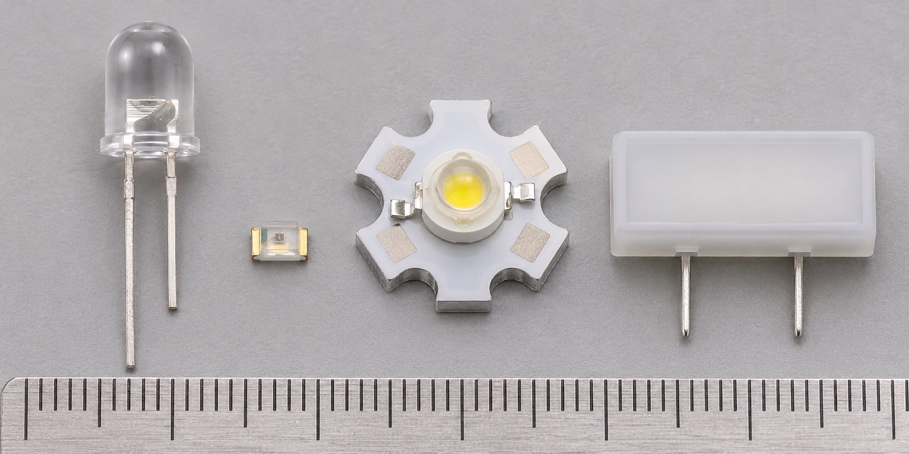
Component images are generated illustrations of package styles; refer to datasheets for exact parts.
These tools use stated assumptions and show their formulas. They are for learning and early prototyping; verify real parts against their datasheets.
How we check the tools →