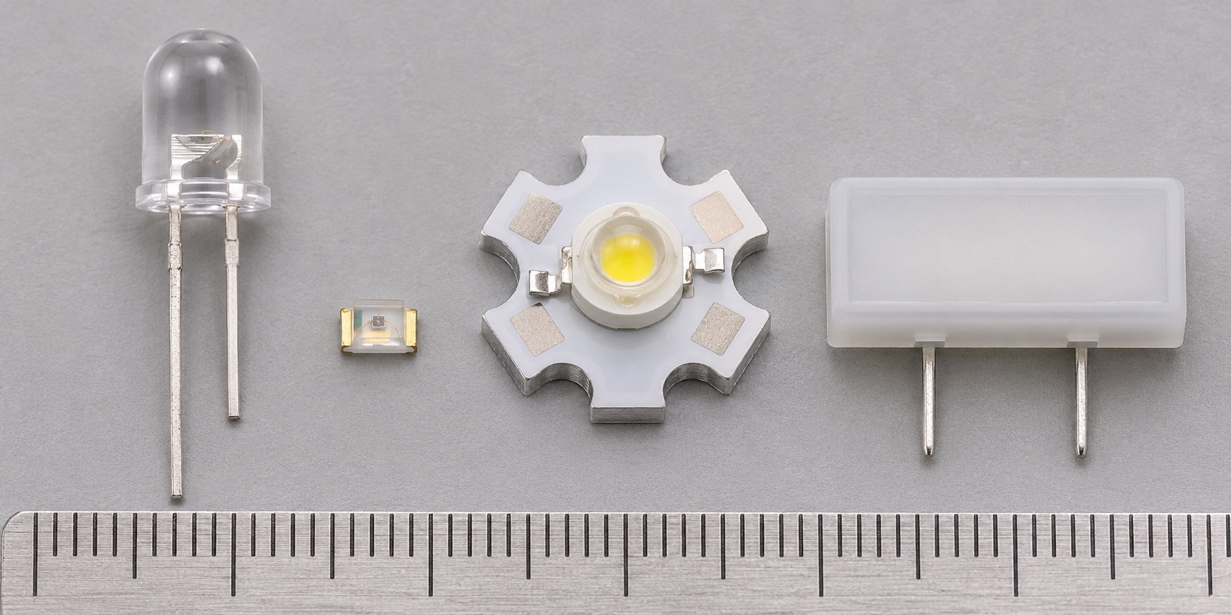
Select a current limit and check LED polarity, forward voltage and thermal limits.
How it works
A small indicator LED is commonly driven through a series resistor. Estimate R = (Vs − Vf) / I, then check the chosen standard value and worst-case tolerances. High-power LEDs generally need a suitable constant-current driver and thermal path.
Types and construction
Through-hole indicators, surface mount indicators and power LEDs differ greatly in optical output, electrical ratings and heat removal. Color alone does not uniquely determine Vf; the actual part and test current matter.
Worked example
Assuming a 5 V supply, one LED at Vf = 2 V and a 330 Ω resistor, the fixed-Vf model gives I ≈ 9.09 mA. Resistor dissipation is about 27 mW. This is a worked estimate; recalculate for the actual LED’s Vf range and supply tolerance.
Reading a datasheet
Check the exact package pinout, forward current, Vf at specified test current, reverse-voltage limit, optical data, ambient-temperature derating and junction-temperature or mounting requirements.
Common mistakes
- Connecting an LED straight across a voltage source without current control.
- Assuming all colors and packages have the same Vf.
- Using the typical Vf as a guaranteed worst-case value.
Explore further
Source and review
Reviewed 18 November 2026 against Cree LED, CLM2D red/amber SMD LED datasheet. Examples are simplified educational models; ratings and pinouts depend on the exact device.