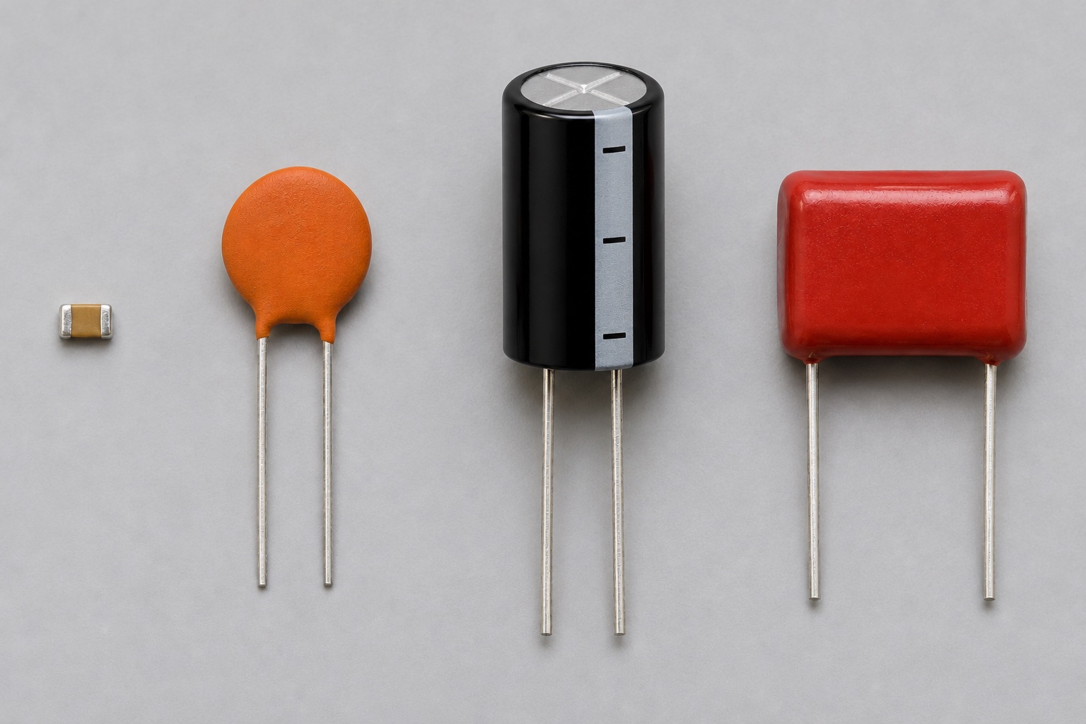
Understand capacitance, voltage rating, polarity, dielectric and effective capacitance.
How it works
The ideal relation is Q = C × V; current flows while voltage changes: i = C × dV/dt. A capacitor can smooth a supply, couple a changing signal or set timing with a resistor. A discharged capacitor can draw a large initial current if the source does not limit it.
Types and construction
C0G/NP0 ceramic capacitors are stable but usually available at smaller capacitance. X5R/X7R multilayer ceramics offer larger nominal values but can lose effective capacitance under DC bias. Aluminum electrolytic and tantalum or polymer capacitors are generally polarized; consult the exact series for ripple and lifetime limits.
Worked example
An ideal 10 kΩ resistor and 100 µF capacitor have a time constant τ = R × C = 1 s. After one τ of charging from an ideal 5 V step, capacitor voltage is about 3.16 V (63.2% of the final value). Leakage, tolerance and DC bias can shift real timing.
Reading a datasheet
Verify voltage rating, capacitance tolerance, dielectric, effective capacitance versus DC bias, temperature range, ESR, ripple current and polarity when relevant. For an electrolytic, also review lifetime at the specified temperature and ripple.
Common mistakes
- Using the printed X7R/X5R value as the effective capacitance at operating voltage.
- Reversing a polarized capacitor.
- Assuming voltage rating alone guarantees low heating under ripple current.
Explore further
Source and review
Reviewed 18 November 2026 against Murata, ceramic capacitor DC bias FAQ. Examples are simplified educational models; ratings and pinouts depend on the exact device.