Components / Diodes

Diodes: Polarity and Basic Operation

Understand forward conduction, reverse blocking, current and recovery ratings.

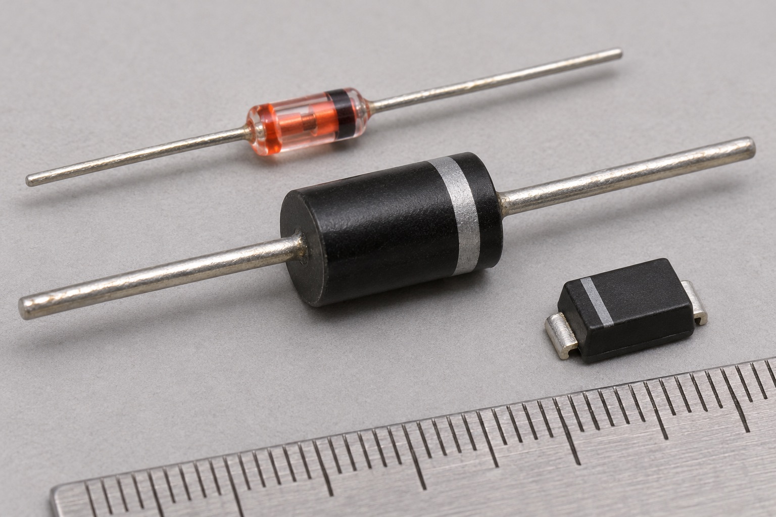
Illustrated diode forms: glass axial signal diode, black axial rectifier with cathode stripe and small surface-mount diode
Appearance illustration of 3 common physical forms. Generated for teaching, not a photograph of the models below; size and markings are not exact. See the in-site model notes for verified details.

Recognise and choose

What forms will you encounter?

01Small glass body, upper area

Glass axial signal diode

How to recognise it
Tiny glass tube with one lead each side and a cathode band.
Use it when
Small-signal steering and switching at modest current.
Check before choosing
Cathode orientation, reverse voltage, current and recovery time.

Model notes on this siteNexperia 1N4148 →

02Black cylinder, centre

Axial power rectifier

How to recognise it
Larger black moulded body with a clear cathode stripe.
Use it when
Rectifying or blocking current where the specified continuous and surge ratings fit.
Check before choosing
Reverse voltage, average current, surge, forward loss and recovery speed.

Model notes on this siteonsemi 1N4007 →

03Small black chip, lower right

Surface-mount Schottky diode

How to recognise it
Tiny moulded chip with a package-specific cathode mark.
Use it when
Low-voltage rectification or fast switching when its leakage and reverse rating are acceptable.
Check before choosing
Exact package marking, reverse voltage, Vf at current, hot leakage and thermal path.

Model notes on this siteNexperia PMEG4010EPK →

At a glance

A diode conducts mainly from anode to cathode when forward biased and blocks in the opposite direction within its reverse-voltage rating.

This guide explains a component family. Check the exact part number and manufacturer datasheet before building.

Key specifications

Forward current
Continuous and surge limits under stated conditions
Forward voltage (Vf)
Drop at a specified current and temperature
Reverse voltage
Maximum specified blocking voltage
Recovery and leakage
Switching behavior and reverse current

Circuit Lab

Put this component into a circuit

How do diode type and polarity alter a simple circuit?

Change
Supply, polarity, forward-drop model and load
Observe
Conduction state, load voltage and diode power

Explore the linked experiments using their stated model assumptions. Device-specific limits still come from the linked datasheets.

How it works

A forward-biased diode has a current-dependent voltage drop, so a fixed 0.7 V model is only a rough circuit estimate. Reverse-biased current is small within the specified range, but excessive reverse voltage can cause breakdown.

Types and construction

Small-signal switching diodes, power rectifiers, Schottky diodes and Zener diodes serve different purposes. Schottky parts can switch quickly and often have lower forward drop, but their reverse leakage and voltage limits still need checking.

Worked example

A 1N4148 can steer a small signal, but it is not a generic high-current rectifier. Its manufacturer datasheet states 100 V continuous reverse voltage and 200 mA continuous forward current under specified mounting conditions; these numbers do not transfer to other “1N4148” packages or suppliers.

Reading a datasheet

Read the exact part number, package and polarity drawing. Check reverse voltage, continuous and surge forward current, Vf at relevant current, leakage at temperature, recovery time and thermal limits.

Common mistakes

  • Treating the stripe or schematic symbol as proof of every package pinout.
  • Assuming a universal 0.7 V forward drop.
  • Using a signal diode at power-rectifier current or ignoring surge current.

Explore further

Source and review

Reviewed 18 November 2026 against Nexperia, 1N4148/1N4448 datasheet. Examples are simplified educational models; ratings and pinouts depend on the exact device.